
Low-Level LED Blinking
I decided to take a pause on Lars’ video series because he was starting to use sensors in his projects. I’ve placed an order for some sensors through Amazon, but they’ll take a few weeks to arrive. In the meantime, I’ve decided to switch to another highly-recommended video series: Modern Embedded Systems Programming taught by Miro Samek.
The first couple of videos walks through the basics of setting up his development environment. He has project files for an STM32 Nucleo board in his Github repo, but he hasn’t actually mentioned it yet in the videos. Seems that the video were recorded only for the TI Launchpad board so far.
However, because of my training so far, I was actually able to replicate his functionality! (with some help from the reference manual, the QWEN LLM, and Miro’s teachings of course)
In video 4, Miro flashed an LED on his board without any libraries.
We did this before by using our trust HAL library in the STM32 environment, but it was definitely interesting to do it without it.
I looked at the project files from Miro and asked Qwen to expand on/explain the comments, because they weren’t as in-depth as I would have liked.
I was able to write this high level comment to explain what we actually needed to do:
/**
* For the Nucleo-F767ZI board, user led 1: LD1 is connected to PB0
* To enable the GPIOB pins, we need to enable the RCC clock register for the port
* then set GPIOB Port 0 to be an output port, in push-pull mode, low speed, with no pull-up/pull-down
* then we need to set the gpio port bit set/reset register(BSRR), pause a bit,
* then reset the BSRR
*/
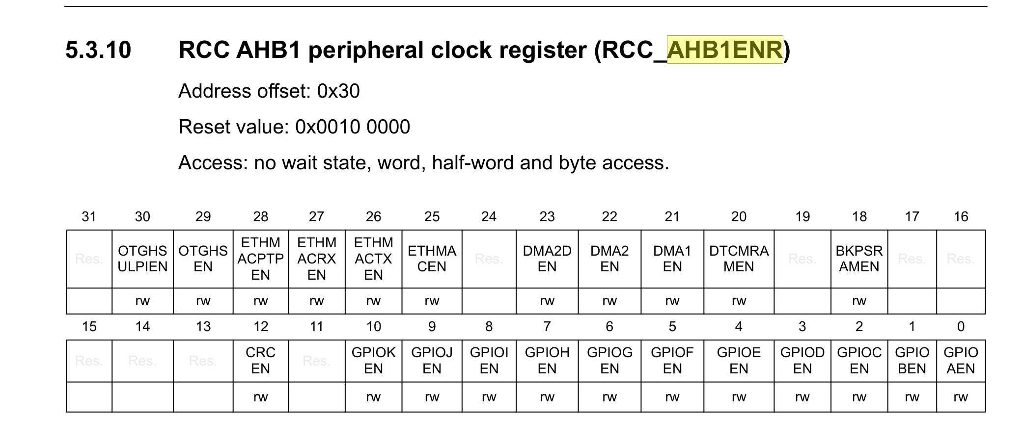
In his board, the RCC register was called the IOPENR register. In my board, it was called the AHB1ENR register. This was fairly easy to find in the reference manual:
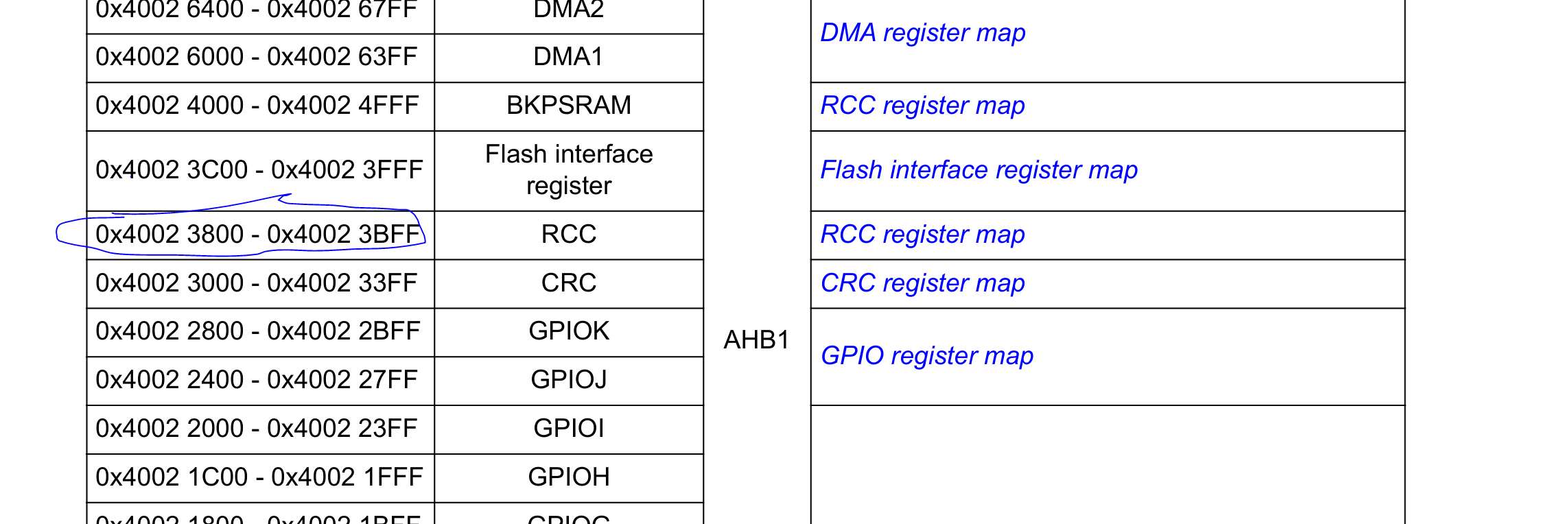
Once I found the register that I needed to modify, I went back to find the base register for the RCC:
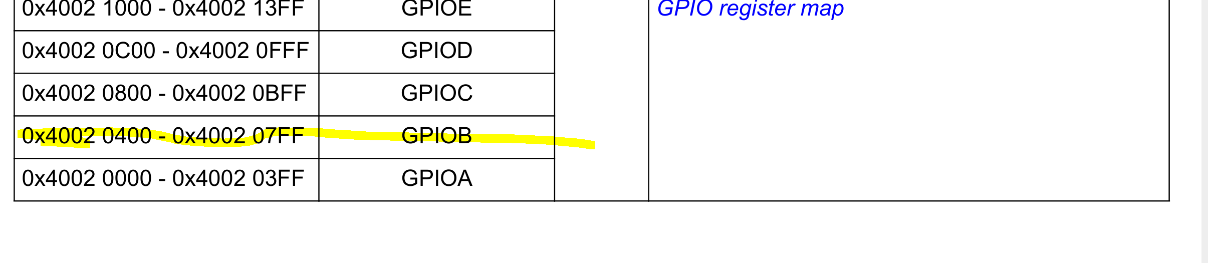
And of course the base register for the GPIOB:
Then I started creating pointers to all the registers that I needed to modify:
// set the base register address for the RCC
unsigned int *rcc_register = (unsigned int *)0x40023800U;
// then add the offset for the RCC AHB peripheral clock register, which controls the GPIOB port
// note that for these offsets, since we are referring to memory addresses, we need to divide by the size of each
// address
unsigned int memory_address_size = sizeof(uint32_t);
rcc_register += 0x30U/memory_address_size;
// then set the flag/bit to enable the RCC for the GPIOB port
*rcc_register |= 0x0002U;
// now set the base register address for the GPIOB bank
unsigned int *gpiob_base_register = (unsigned int *)0x40020400U;
// set the register address for the gpio port mode register (offset 0x00)
unsigned int *gpiob_port_mode_register = gpiob_base_register+(0x00U/memory_address_size);
// set the register address for the gpio port output type register (offset 0x04)
unsigned int *gpiob_port_type_register = gpiob_base_register+(0x04U/memory_address_size);
// set the register address for the gpio port output speed register (offset 0x08)
unsigned int *gpiob_port_speed_register = gpiob_base_register+(0x08U/memory_address_size);
// set the register address for the gpio port pull-up/pull-down register (offset 0x0C)
unsigned int *gpiob_pull_up_down_register = gpiob_base_register+(0x0CU/memory_address_size);
// set the register address for the gpio port bit set/reset register
unsigned int *gpiob_port_bit_set_reset_register = gpiob_base_register+(0x18U/memory_address_size);
I initially forgot how to do pointer math, but Qwen reminded me. Basically, besides just adding the offset to the base address for the register, we also need to divide the offset by the size of each address.
Once I had the pointers set up, it was fairly straightforward to deference the pointer and set the flags that I actually wanted:
// set the flags for the configuration that we want
*gpiob_port_mode_register |= 0x0001U;
*gpiob_port_type_register |= 0x0000U;
*gpiob_port_speed_register |= 0x0000U;
*gpiob_pull_up_down_register |= 0x0000U;
And then to loop and toggle the port for the LED on and off:
while (1) { // endless loop
    *gpiob_port_bit_set_reset_register = 0x00000001U; // GPIOA BSRR register

    int volatile counter = 0;
    while (counter < 500000) {  // delay loop
        ++counter;
    }

    *gpiob_port_bit_set_reset_register = 0x00010000U; // GPIOA BSRR register
    counter = 0;
    while (counter < 500000) {  // delay loop
        ++counter;
    }

}
It felt really good to get this working on my own!