
UART (Universal Asynchronous Receiver/Transmitter)
Video 16 covered UART, our first method of transmitting and receiving data.
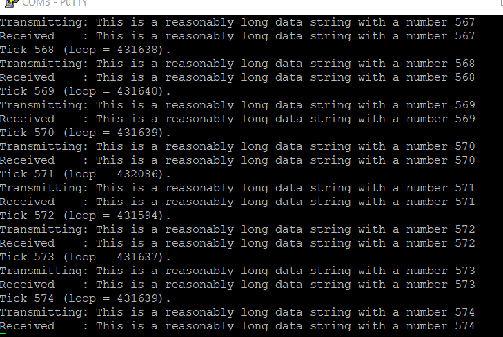
I’m glad Lars used a method to transmit and receive on the same MCU, because I only have one board right now. It seems like a relatively straightforward concept. You configure two lines: one for Tx and one for Rx, and you set them at the same baud/symbol rate. Receiving definitely seems to be more difficult that transmitting, because you need to buffer the data and look for end characters. However, his method was fairly understandable. We seemed to be appending characters to a string until we received a special character (0), at which point we process the entire received string.
I struggled for a bit with the pin configuration. The default pins on my board for UART4 were PA_11 and PA_12, which don’t have headers attached. I thought I could stick pins in them without soldering, but it didn’t seem to make a connection. I kept getting this error, because I believe the pins were floating:
UART4 Error Code: 0x0000000a
- Noise Error
- Overrun Error
Once I reassigned the Tx and Rx pins to PC_10 and PC_11, it worked perfectly!

I hope it’s as easy to use this when I get a second MCU. This seems like a really good candidate for transmitting small amounts of data between two boards. Can’t wait to try. I wonder how the clock rates need to match between the boards?