
A Temporary Stop for Some Circuit Refreshes!
Doh! On video 4 of the playlist, CMTEQ immediately jumped into a pre-assembled circuit on a breadboard, where we would be building a binary counter.
This seems like a great tutorial, but I needed to refresh myself on building basic circuits before I could follow along with this.
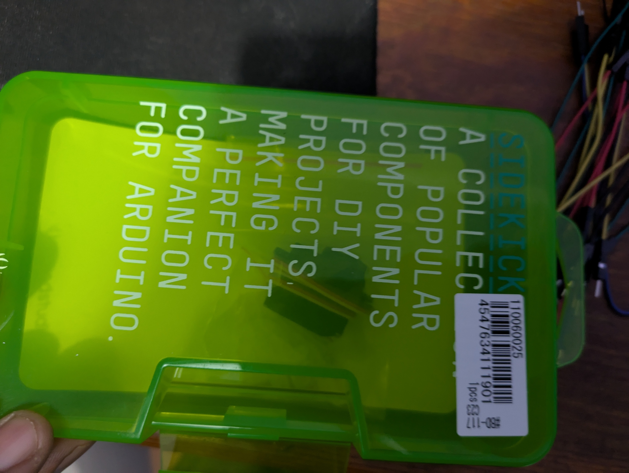
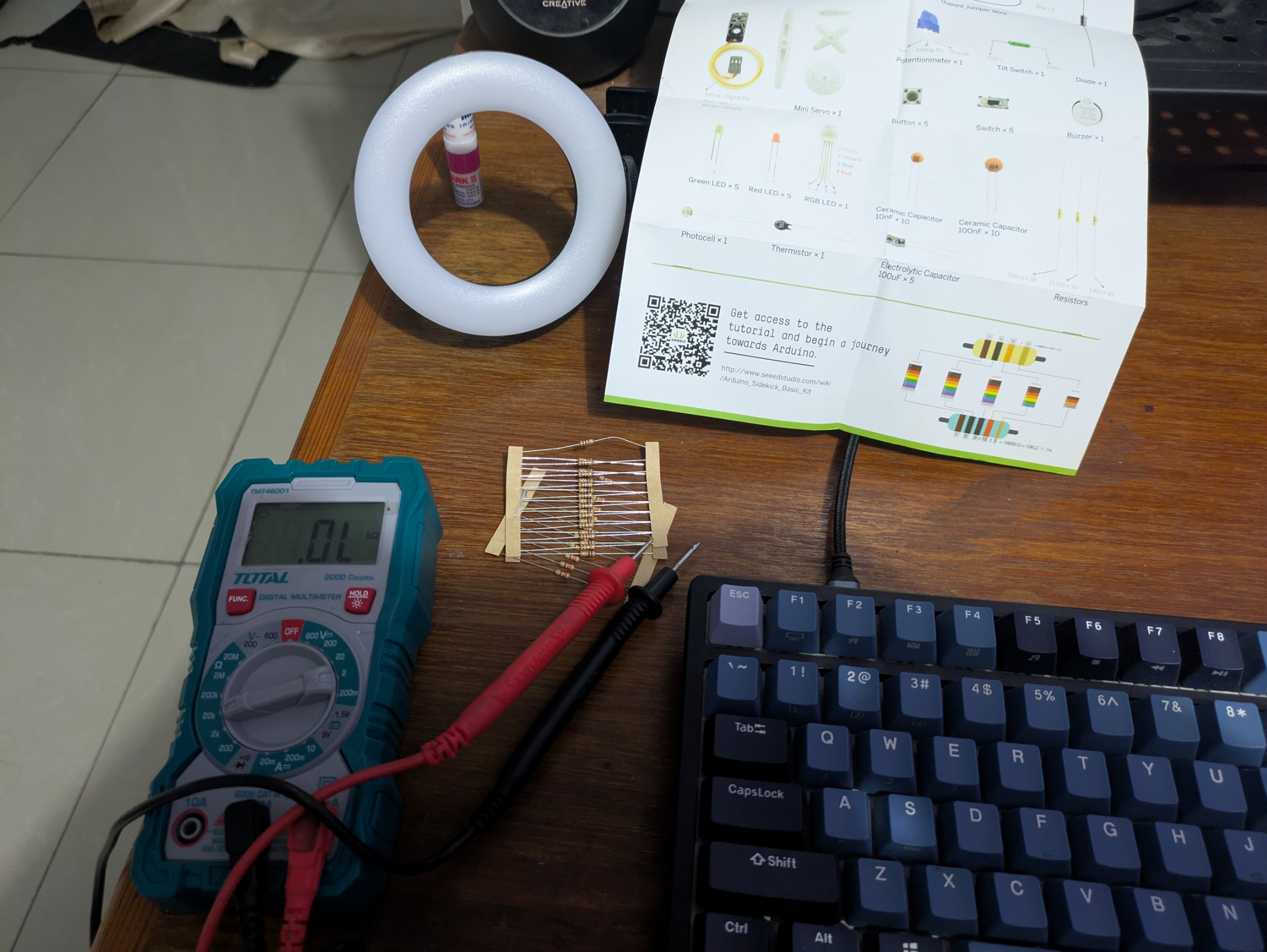
Luckily, I had bought this basic Sidekick kit when I picked up my STM32 board. The first step was to remember how to read resistor colors to determine their values!
I found my multimeter, and got to work testing the resistors. With the color guide handy, it wasn’t too bad at all.
I sort of remembered how to connect a basic circuit to light an LED, but I figured I should follow a basic tutorial (just to make sure I wouldn’t blow up the board)
I found this small video: by Sean Kennedy
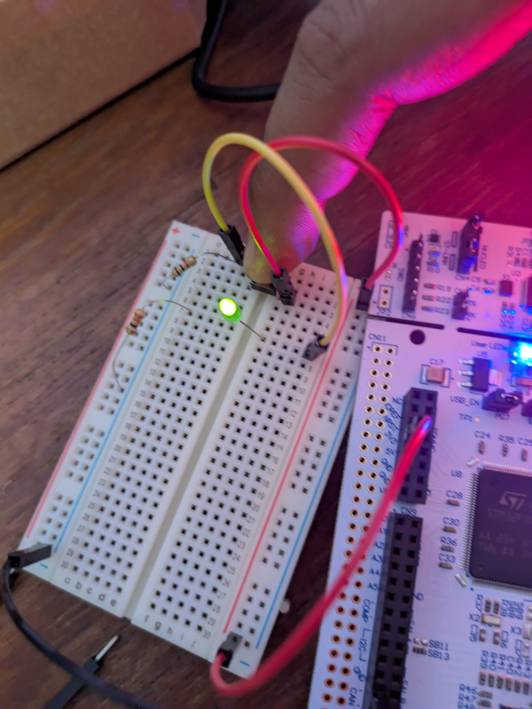
I wired basically the same circuit as the video, and it worked!
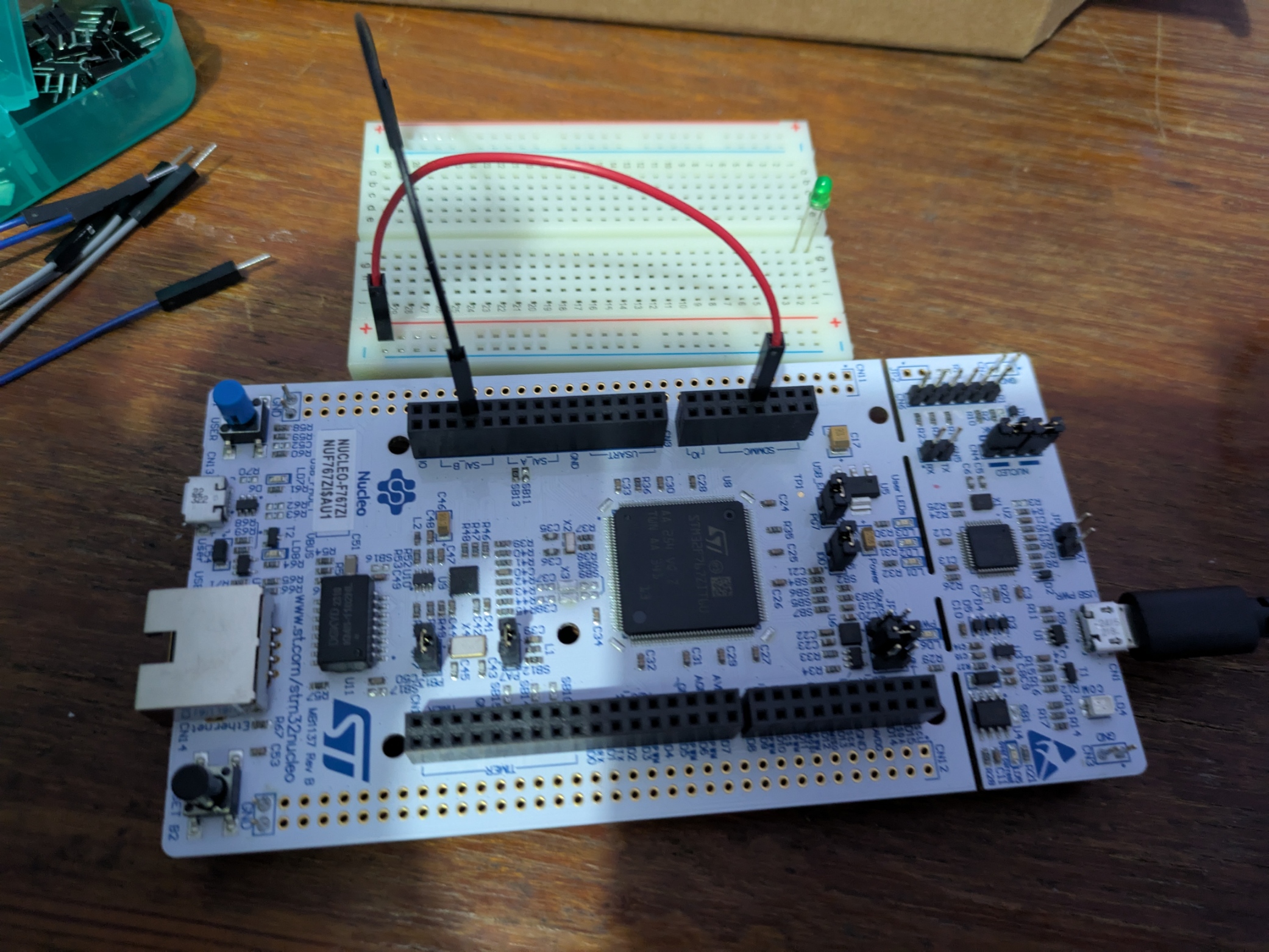
I started off by connecting the 3.3V power supply and ground pins from my STM32 board to the breadboard.
Then I wired the other components (resistors, switch and LED)
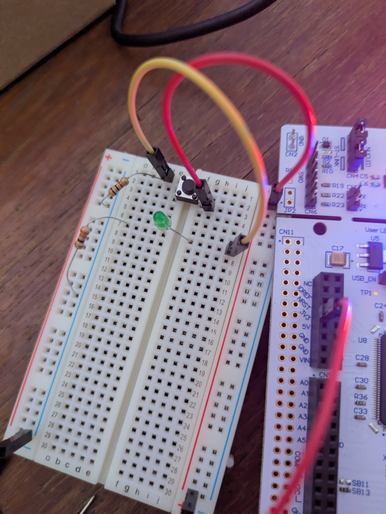
The first time I pushed the button, nothing happened. It took me a while to remember that LEDs are polarized (they have to be wired in the correct direction)
Apparently, the longer leg is the anode(+), and the shorter leg is the cathode(-).
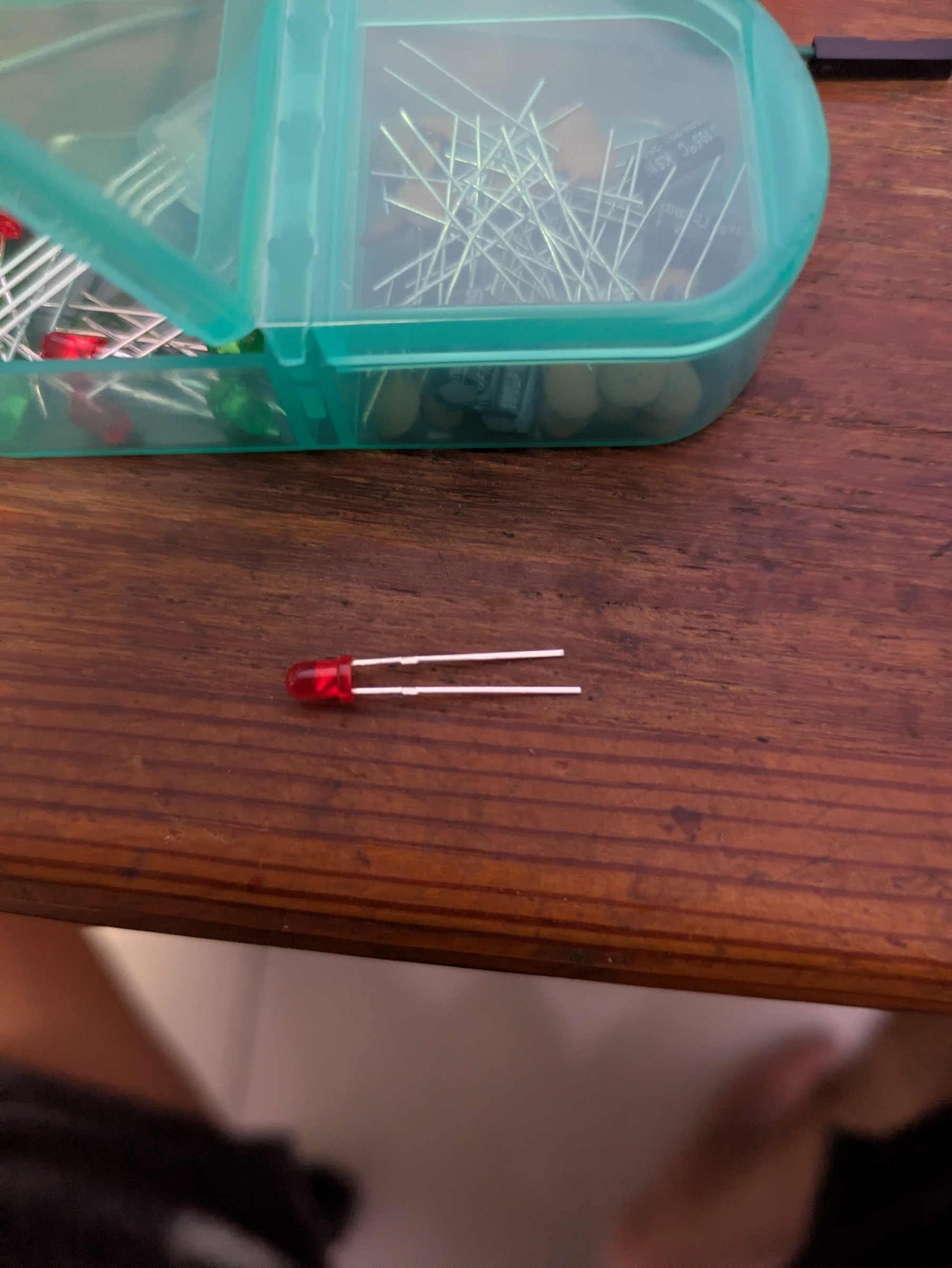
I switched the direction of the LED legs, and it worked!
The next step is to send a basic GPIO signal out to light the LED, instead of using the pushbutton.