
Starting with the ESP32-C6
While I’m waiting for my parts to reach in, I thought it would be fun to try my hands at my new board: An ESP32-C6 DevKitC-1.
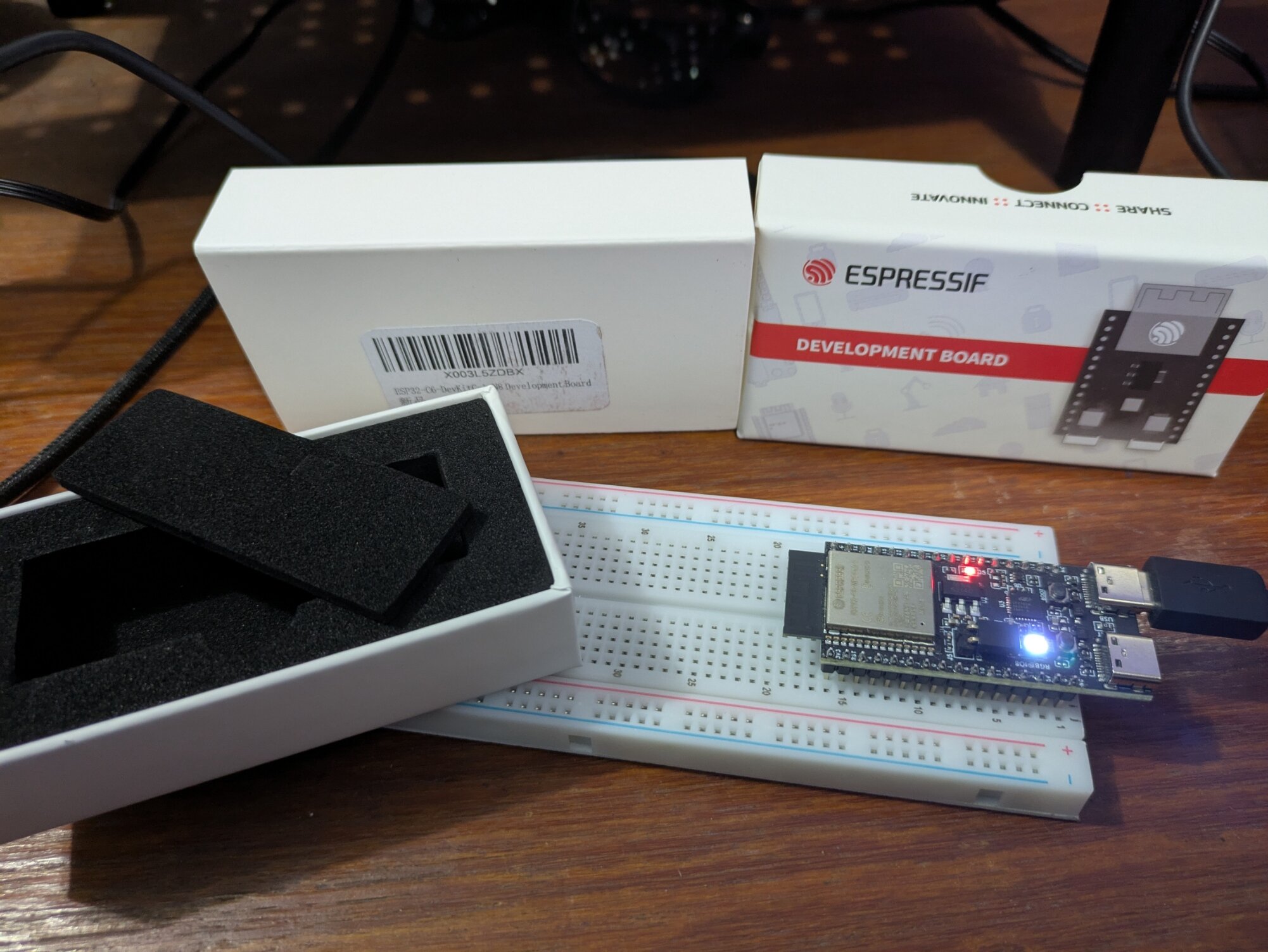
The packaging was amazing! It made it feel like a board twice its price for sure (I got it for just $15 USD on Amazon).
The official instructions on the website turned out to be pretty self explanatory for installing the ESP IDF (Espressif IoT Development Framework). However, as usual, I tried to do my own thing and ended up wasting a bunch of hours. 😅
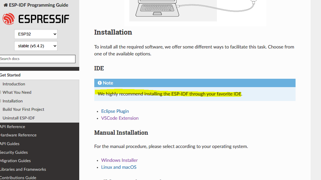
I thought it would be easier to use the manual installer instead of installing the framework through VS Code. Unfortunately, the manual install seems to only install the command line tools, so I definitely recommend following their instructions and using the VS code extension to install everything you need.
Once I had the extension set up in VS code, I created two projects for the two ‘getting started’ projects in their example code.
For the first ‘hello world’ project, I connected my board using a regular USB C cable and did a cursory reading to understand a bit about what the project was doing.
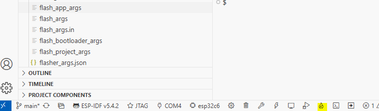
I then clicked through the buttons at the bottom of my VS code window (to set up my board, my com port etc.) and once I clicked the build,flash and monitor button, it just worked!
Emboldened by this immediate success, I set up another project for my ‘blinky’ example, and I tried again. Unfortunately, this one had less success. The code was also a bit more complicated, since it had a bunch of these precompilation directive blocks:
#ifdef CONFIG_BLINK_LED_STRIP

static led_strip_handle_t led_strip;

....

#endif
Luckily, most people start their ESP32 journey with these tutorials and I have a fairly standard devkit board from EspressIf, so I found a thread that gave me the required configs:
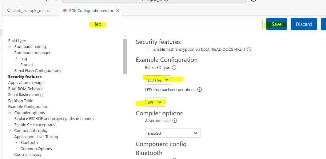
We basically had to use the SDK Configuration Editor (available from the bottom bar as a button or in the extension settings) to set the LED as a strip, and to set it to use SPI to communicate with the board.
This configuration seemed to set some values for some macros in the ESP header files.
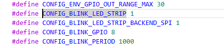
Once I built and flashed this config, the LED started to blink!
As a next step, I want to learn a bit more about how this framework operates, so I’ll need to do some more reading and Youtube watching. I want to learn how to configure tasks and if I can reuse the ‘boot’ button that I’m seeing on the board. Perhaps I can use the button to change the colour of the LED?